|
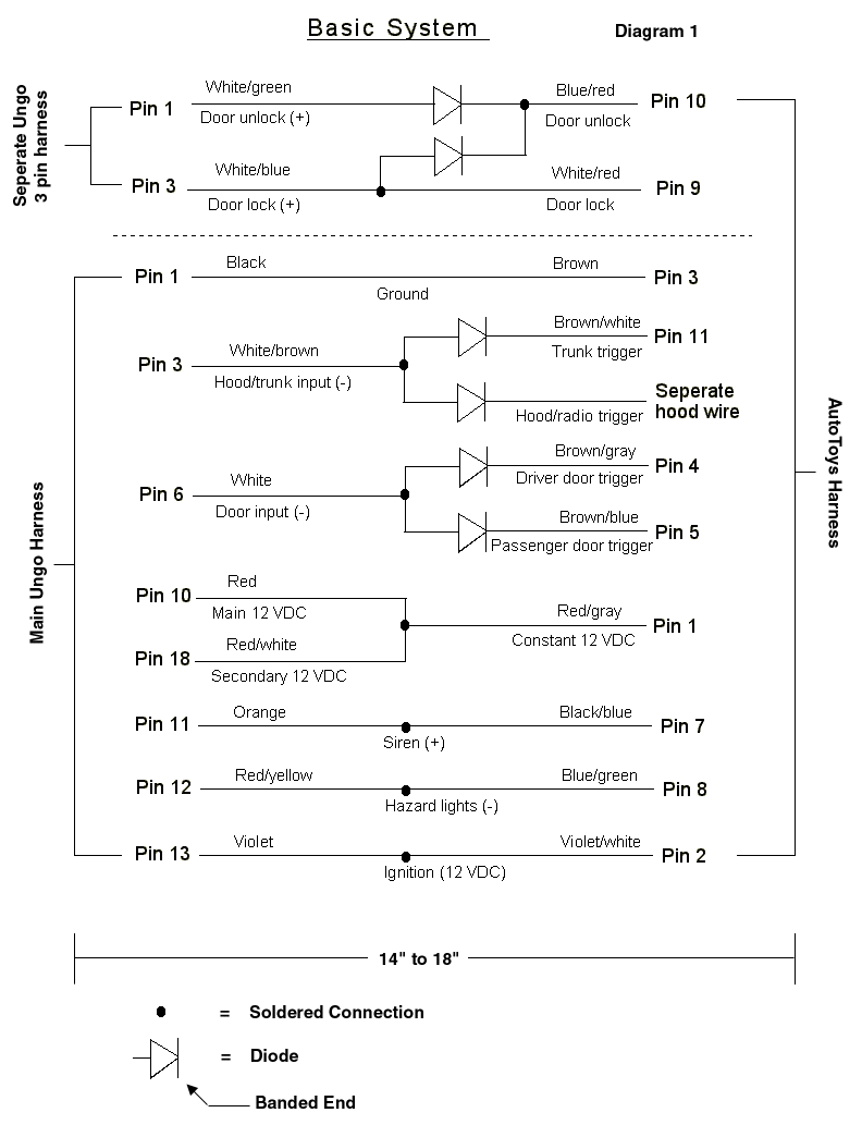
Basic System Diagram Created by Ziggy updated 6-2000 Wire Harness Step 1 Diagram 1 Tips: Practice soldering connections before doing real thing, leave gun plugged in 10 minutes before using, letting it get hot Use the micro clips ( see parts list) for heat dams to protect diodes and wire insulation from getting hot. Use the heat shrink tubing to cover bare wires and diodes. Cut heat shrink to the right length, put it on the wire before you solder, after you solder slide it over the bare wires and heat with hair dryer. Make the harness about 14-18 inches long (from end of UNGO alarm harness to end of autotoys harness) cutting excess wire off of the alarm side leave two wires with fuse, 6 inches longer. The reason for this will be described in final step. Follow the wiring in diagram 1, the bullets represent a soldered connection, always make sure the diodes are going in the right direction (banded end facing the autotoys harness). Make sure you are following the diagram to the tee. When done I suggest checking with a ohm meter and double checking that you have the wires connected per the diagram Last thing to note is separate hood wire (see wire diagram) make this about six inches long, it will be plugged into the separate hood wire behind the glove box in the future GOOD LUCK 
|
|
Basic System Diagram Book Of UNGO Part 1 Plan Ahead~~ Part 2 So begins the search for parts~~ Part 3 Siren Placement~~ Part 4 Placing the LED, Cutoff Switch and Space Sheild ~~ Part 5 Glovebox Kama Sutra~~ Part 6 UNGO CPU and Logic Sensor ~~ Part 7 Hardwiring~~ Part 8 Routing the V1 Power, Above and Below~~ Part 9 Setting Levels~~ Additional Information: Removing Console, Bumper Siren, UNGO Z3 Schematic, Wire Harness Basic System Diagram, Ziggy's UNGO Install |
 Esmerelda's
Home Page Esmerelda's
Home Page |